
3.4
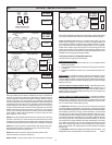
Owner's of the Schumacher Battery Charger SE-3000 gave it a score of 3.4 out of 5. Here's how the scores stacked up:
6
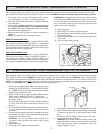
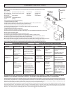
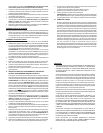
1. First place the charger on it side.
2. Next mount the mounting foot FIG. A with (2) 1/4-20 screws, or FIG. F with (2) 10-32 screws.
3. Next pound the axle firmly into an axle cap using a hammer FIG. B.
4. Slide one wheel onto the axle with hub facing in, as shown in FIG. C.
5. Poke above assembly thru holes in charger back until axle sticks out of the other end.
6. Turn charger on its other side.
7. Slide wheel and pound cap onto the axle end.
8. Next turn the charger right side up onto its foot and wheels.
9. Remove the (2) top screws from each side of the charger, line up the handle and reinstall the screws FIG. E.
Wheel Charger Assembly Instructions: (Instrucciones De Armado)
NOTE: Charger must be assembled before operating (Ante de la operación la unidad debe estar armada)
Parts (Piezas)
(2)10-32 screws (tornillos de corte rosca 10-32)
(2) 1/4-20 screws (tornillo de corte rosca 1/4-20)
(2) wheels(ruedas)
(2) axle caps (tapas del eje)
(1) handle(mango)
(1) mounting foot (pedestal de montaje)
(1) axle (del eje)
Tools necessary (Herramientas Necesarias)
5/16" wrench (Llave de 5/16")
3/8" wrench (Llave de 3/8")
Hammer (Martillo)
Screwdriver (Destornillador)
L. ASSEMBLY INSTRUCTIONS
LIMITED WARRANTY
SCHUMACHER ELECTRIC CORPORATION, 801 BUSINESS CENTER DRIVE, MOUNT PROSPECT, ILLINOIS, 60056-2179 MAKES THIS LIMITED
WARRANTY TO THE ORIGINAL PURCHASER AT RETAIL OF THIS PRODUCT. THIS LIMITED WARRANTY IS NOT TRANSFERABLE.
Schumacher Electric Corporation warrants this battery charger for 3 years, and the transformer and rectifiers for 5 years from date of purchase at retail against defective material
or workmanship. If such should occur, the unit will be repaired or replaced at the option of the manufacturer. It is the obligation of the purchaser to forward the unit together with
proof of purchase, transportation and / or mailing charges prepaid to the manufacturer or its authorized representative. This limited warranty is void if the product is misused,
subjected to careless handling, or repaired by anyone other than the factory or other authorized factory representative. The manufacturer makes no warranty other than this
limited warranty and expressly excludes any implied warranty including any warranty for consequential damages.
This is the only express limited warranty and the manufacturer neither assumes nor authorizes anyone to assume or make any other obligation towards the product other than
this express limited warranty. The manufacturer makes no warranty of merchantability or fitness for purpose of this product and expressly excludes such from this limited
warranty. Some states do not allow the exclusion or limitation of incidental or consequential damages or length of implied warranty so the above limitations or exclusions may not
apply to you. “This warranty gives you specific legal rights, and you may have other rights which vary from state to state.”
PROBLEMA
CAUSA POSIBLE SOLUCION
La pinzas no están
haciendo buen
contacto.
Voltaje de la bateria
demasiado bajo.
El tomacorriente CA
no tiene electricidad.
Mala conexión
eléctrica.
El disyuntor de
circuito está
funcionando.
La batería está
defectuosa.
Batería demasiado
descargada, pero
buena.
Invertir las conexiones
en la batería.
El medidor no indica
(cordón CA
desenchufado)
El cargador no se
enciende cuando
está bien conectado.
El cargador hace
ruido (“clic”)
Primero coloque el cargador de lado.
A continuación monte el pedestal FIG. A con (2) tornillos 1/4-20.
A continuación golpee firmemente el eje dentro de la tapa del eje usando un martillo, FIG. B.
A continuación deslice las ruedas dentro del eje; los cubos deben estar orientados hacia adentro, FIG. C.
A continuación golpee la otra tapa del eje dentro del otro extreme del eje.
A continuación coloque el conjunto del eje dentro del fondo del cargador según se muestra en la FIG. C.
Monte el eje en el fondo del cargador usando los dos tornillo de corte de rosca 10-32 según se muestra en la FIG. D.
A continuación gire el cargador de la batería con el lado derecho hacia arriba sobre su pedestal y ruedas.
Saque los dos tornillos superiores de cada lado del cargador; alinee el mango y reinstale los tornillo. FIG. E.
Mover las pinzas hacia uno y
otro lado para lograr mejor
contacto.
Enchufar el cordón CA al
tomacorriente; ahora el
medidor debe indicar.
Enchufar una lámpara para
verificar si hay voltaje.
Revisar las conexiones,
mover hacia uno y otro lado
para lograr mejor contacto.
Puede estar en la posición
errónea del interruptor.
Hacer revisar la batería.
Dejar cargando hasta que la
batería tenga oportunidad de
recuperarse lo suficiente para
tomar carga. Si se demora
más de 20 minutos, parar de
cargar y hacer revisar la
batería.
Apagar el cargador y
corregir las conexiones de
los conductores.
TROUBLESHOOTING
If a problem does occur, check the following:
PROBLEM POSSIBLE CAUSE SOLUTION
No Meter Reading Clips are not making Rock clips back and
(AC Cord Unplugged) a good connection. forth for a better connection.
Battery voltage is too Plug AC line into outlet.
low. Meter should now indicate.
2 amp charge rate None, meter will not indicate
being used. here.
Charger will not turn AC outlet is dead. Plug in a lamp to check for
on when properly voltage.
connected. Poor electrical Check connections, rock
connection. back and forth for a better
connection.
Clicking noise from Circuit breaker is May be in the wrong switch
charger. cycling. position
Battery is defective. Have Battery checked.
Severely discharged Allow charging to continue
battery but otherwise until battery has a chance
a good battery. to recover sufficiently to take
a charge. If more than 20
min. stop charging and have
the battery checked.
Reverse connections Shut off charger and correct
at battery. lead connections.
Fig. E
Fig. F
Fig. B
AXLE CAP
Fig. A
Fig. D
AXLE BRACKET
HUBS MUST
FACE IN
Fig. C
LOCALIZACION DE AVERIAS
Si ocurre algún problema, verificar lo siguiente:


Find Your Products By Category
Please Login
